This is an old revision of the document!
Table of Contents
VGARC, Text-based VGA Adapter for RC2014
Introduction
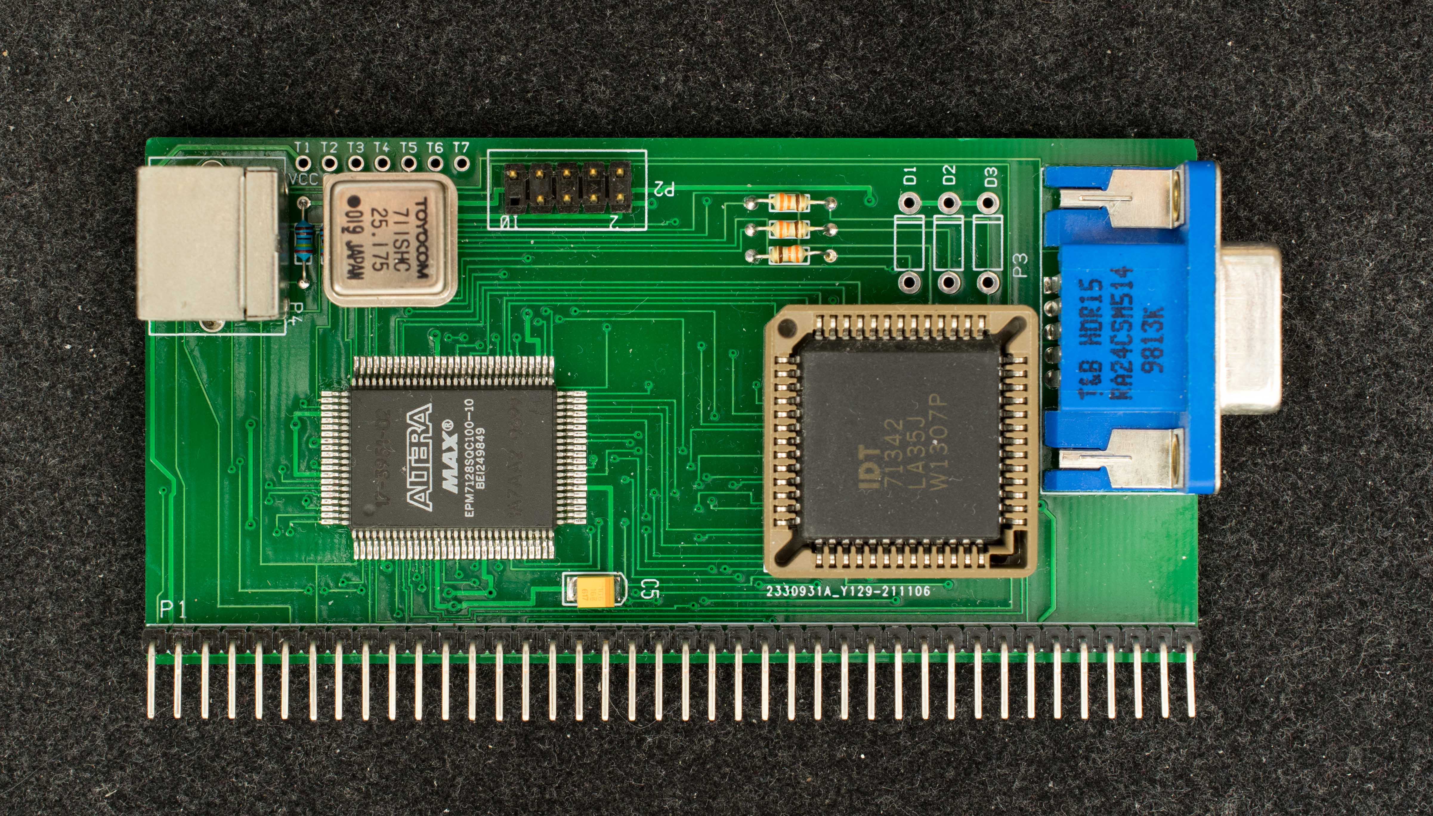
VGARC, rev1 replaces the previous exploratory rev0.1 and prototype designs. VGA rev1 is based on 4K of dual-port RAM shared between RC2014 bus and on-board video display circuitry. The 4K dual-port RAM issplitted into 1K of font tables and 3K of text memory. Both font tables and text memory can be accessed at any time without causing display flickering. VGARC also has a PS2 keyboard interface.
Features
- 4K bytes of dual port RAM to simplify communication between Z80 and video display logic
- Altera EPM7128S CPLD generates VGA video timings and PS2 keyboard interface
- 8×8 pixel font
- User programmable Font lookup table for 128 text characters
- Display 48 lines, 64 characters per line
- Hardware scroll register
- Hardware cursor capability
- Video text and font accessible in I/O space, default I/O addresses 0x0-0xF
- PS2 keyboard interface
Theory of Operation
VGARC rev1 has two interfaces, PS2 keyboard interface and VGA video interface.
PS2 Keyboard Interface
PS2 keyboard communicated to VGARC via two wires, PS2Clock and PS2Data. Data flow only from PS2 to VGARC, commands from VGARC to PS2 keyboard is not implemented. PS2Clock is a bidirectional signal between VGARC and PS2 keyboard, while PS2Data is an input from PS2 keyboard to VGARC. In idle state both PS2Clock and PS2Data are high. When a key is pressed, PS2 keyboard serially transmit data on PS2Data line and strobe PS2Clock for each data bit. Once a full byte of keyboard data is received with correct parity, the data is stored in hold register at location 0xF4 and least significant bit of 0xF5 is set to indicate keyboard data ready. VGARC pull down PS2Clock to prevent further transmission of keyboard data. Once Z80 read the keyboard data in hold register, the status bit is cleared and PS2Clock is negated to allow more incoming data from PS2 keyboard.
There are two I/O registers associated with PS2 keyboard; PS2 data register is a read-only 8-bit register located at I/O address 0xF4 located. PS2 status register is read-only with bit 0 set to indicate data ready and bit 0 cleared to indicate no data. Bit 1 to bit 8 of PS2 status register are same values as bit 1 to bit 7 of PS2 data register. PS2 status bit is cleared when PS2 data is read.
VGA Video Interface
The VGA video interface is comprised of a 4K dual-port RAM and VGA timing generator in CPLD. One side of the dual-port RAM is connected to RC2014 bus as 4K of I/O space with default addresses of 0x0-0xF; the 4K space is divided into 3K of text memory (I/O addresses 0x0-0xB) and 1K of font tables (addresses 0xC-0xF). The other side of the dual-port RAM is accessible by the CPLD video generator only. The video generator continuously read the 3K text memory sequentially starting from the first location to end of 3K memory; the text value is used to look up the corresponding font table located at the top 1K of the dual-port RAM; and the bit patterns from the font table is loaded into a shift register that shifts data out at 25.175MHz pixel rate
Design Information
Schematic
Gerber photoplots
CPLD design file
