Home » RBC Forums » General Discussion » Interested in a Z280 SBC (Z280 SBC retrobrew (CPU280 Revival))
( ) 1 Vote ) 1 Vote
|
|
|
|
|
|
| Re: Interested in a Z280 SBC [message #2924 is a reply to message #2922] |
Sun, 28 May 2017 08:13   |
 snhirsch_gmail.com
Messages: 63
Registered: May 2017
|
Member |
|
|
Wayne W wrote on Sat, 27 May 2017 13:52snhirsch_gmail.com wrote on Sat, 27 May 2017 06:55FYI: It does appear that fast GAL parts can be problematic. I originally used Lattice 16V8 7ns parts in all four locations and found that the board was unable to count the full memory complement until it had been on for about 10 minutes or was run at reduced voltage. Suspecting a race condition, I replaced the CAS GAL with a National 16V8 15ns part. The problem is gone. It now counts all 2048k from a cold start at full voltage. It's possible my unit is an outlier, but it might be worth advising future builders to stick with 15 ns devices. Digikey and Mouser don't appear to stock the slower devices, but they are available from Unicorn Electronics. I've found Unicorn to be a great source for ICs. They stock all but one of the parts on the CPU280 BOM (I had to pickup the 74AS158s from DigiKey).
Different PLD speeds could certainly make a difference, but note that I have been using 7.5ns Atmel devices from the start and my system has always been rock solid. No doubt a combination of tolerances, but I would not conclude that 15ns PLDs are the answer as a general rule.
-Wayne
As I said, I'm not an electrical engineer nor a computer designer. All I know is that my symptoms were characteristic of a timing violation and the slower parts solved it. Just out of curiousity, what brand and speed of memory are you using on your board?
|
|
|
|
|
|
|
|
| Re: Interested in a Z280 SBC [message #2928 is a reply to message #2927] |
Mon, 29 May 2017 18:34 |
 |
lowen
Messages: 226
Registered: August 2016
Location: Western NC USA
|
Senior Member |
|
|
Ok, I have sent a couple of PMs to some who expressed interest in building a CPU280 once the beta period was complete. I honestly was a bit concerned with the troubles Steven was having, but his eventual success, as well as the successes by all the others who have built and collaborated on the CPU280, and with Wayne's github hosting working and usable EPROM and disk images, I believe we're ready to be in more of a production mode. Of course, for the hobbyist, 'production' has a different definition than it would for a commercial manufacturer, and I'm still getting docs and stuff together, especially the build notes that have accumulated in this thread.
If those who I PMed get a board apiece, I will have 4 boards available for sale (but I can get ten more within about a week). PM me if you're interested in purchasing a bare board or a board plus the harder-to-find parts and/or the programmable parts.
--
Bughlt: Sckmud
Shut her down Scotty, she's sucking mud again!
[Updated on: Mon, 29 May 2017 18:35] Report message to a moderator |
|
|
|
| Re: Interested in a Z280 SBC [message #2933 is a reply to message #2927] |
Tue, 30 May 2017 03:47 |
Jonas
Messages: 77
Registered: October 2015
|
Member |
|
|
snhirsch_gmail.com wrote on Sun, 28 May 2017 15:01Wayne W wrote on Sun, 28 May 2017 09:07snhirsch_gmail.com wrote on Sun, 28 May 2017 08:13
As I said, I'm not an electrical engineer nor a computer designer. All I know is that my symptoms were characteristic of a timing violation and the slower parts solved it. Just out of curiosity, what brand and speed of memory are you using on your board?
Toshiba, 60ns
Ah, that may be why your board works with 7 ns. parts! My original memory was 80 ns, resulting in a machine that barely would boot after considerable warmup. Lamar sent me 70 ns. memory, which worked quite a bit better although still required warmup to recognize all the memory. Moving to the slower GAL brought the 70 ns parts to full life. If I had 60 ns it might have been fine with the 7 ns GALs.
More hints about this problem here:
https://www.retrobrewcomputers.org/doku.php?id=boards:ecb:vg a3:construction
|
|
|
|
|
|
| Re: Interested in a Z280 SBC [message #2950 is a reply to message #2934] |
Sat, 03 June 2017 13:15 |
|
lowen
Messages: 226
Registered: August 2016
Location: Western NC USA
|
Senior Member |
|
|
Update for 6/3/2017:
New pics! Here's what I'm shipping as the board+hard-to-find+programmables kit, and a new pic of my older CPU280 with newer EPROM and GAL16V8D's (please note that yes, I am aware that the Z280 socket is rotated 90 degrees; the Z280 is oriented correctly for the board, though not for the socket, which makes swapping Z280's for testing a bit fun)  . .
The Brother P-Touch PT-P700 PC-connected label printer does nicely, with the 3.5mm-wide TZe-N201 working well for labelling the GAL16V8's and the regular 12mm TZe-2312 tape working well for the EPROMs. Note that the checksum I'm printing on the EPROM is the negated checksum in big-endian form. (generated with srec_cat's checksum-neg-b-e function. A simple shell script I use to generate the checksum is attached, and it requires the SRec tools).
Also, the four RAM's came back from Steve; they are actually 60ns parts, not 80. So now I'm really confused, as they aren't too slow. I'm running OKI 60ns RAMs in mine with 15ns Lattice GAL16V8Ds. All kits from this point (including the three I put together today) will be shipping with OKI 60ns parts that are new-old-stock in OKI factory sealed tubes..
Steve, thanks for the pointers on the construction!
EDIT: Tested and packaged for shipment three kits today. I programmed five sets of GAL16V8s and 27C256 EPROMS, so I have one set of programmables left and ready to ship (one is running in my CPU280). I had one GAL16V8D out of 21 fail programming (programmer told me it went into current limit, short circuit), but no other tested parts failed. All three Z280's tested ok; all three SMC FDC's tested ok; all EPROMs booted and ran. To test the RAM and the FDC I use a utility disk image in A: on my HxC, and run 'PIP E:=A:*.*' and let it run to completion. C: is a scratch drive, and testing FDC writes is accomplished by 'PIP C:=A:*.*' running to completion.
--
Bughlt: Sckmud
Shut her down Scotty, she's sucking mud again!
[Updated on: Sat, 03 June 2017 13:33] Report message to a moderator |
|
|
|
| Re: Interested in a Z280 SBC [message #2952 is a reply to message #2950] |
Sat, 03 June 2017 15:58 |
snhirsch_gmail.com
Messages: 63
Registered: May 2017
|
Member |
|
|
Dang. Sorry about that. My eyesight is not as good as it used to be! Not sure we'll ever completely understand the failure mode on my board. It's unlikely to be the CPU or EPROMs, since those were changed out (several times in the case of the CPU). All the tolerances here must have added up in the wrong direction . I'm pleased at how smoothly it runs now. Biggest surprise is a DS1287 from my parts drawer (with date code in 1992) that's still ticking 25 years down the road.
[Updated on: Sat, 03 June 2017 16:00] Report message to a moderator |
|
|
|
| Re: Interested in a Z280 SBC [message #3113 is a reply to message #1189] |
Mon, 26 June 2017 09:03 |
|
lowen
Messages: 226
Registered: August 2016
Location: Western NC USA
|
Senior Member |
|
|
Alright, I've gotten a few requests to see about getting the REH-ECB-IDE, the companion IDE board for the CPU280, re-produced. I do have the raw gerbers from Tilmann, and if there is enough interest (if I can get commitments and preferably payment for seven boards) I'll get a run of ten (or more, if more than ten are wanted) made. I already know of five, including one for myself.
I'm very much interested in getting both the PropIO and the VGA3 workable as consoles, and ideally I'd like it to be auto-selectable or configurable with configuration stored in the DS1287 RTC (default to serial on the Z280's UART). I'd like to see a driver for other IDE/SD/CF devices, too, especially the PropIO's SD card.
But to be vintage-accurate, the REH-ECB-IDE needs to be re-produced anyway, though.
Thoughts?
--
Bughlt: Sckmud
Shut her down Scotty, she's sucking mud again!
|
|
|
|
|
|
|
|
|
|
|
|
| Re: Interested in a Z280 SBC [message #3118 is a reply to message #3117] |
Mon, 26 June 2017 12:29 |
|
lowen
Messages: 226
Registered: August 2016
Location: Western NC USA
|
Senior Member |
|
|
Unless I've miscounted, I get to nine including Paul. I had posted on comp.os.cpm about it, and got a couple of replies, with interest in three IDE boards in those two replies; then one for me, one via PM here, snhirch and wayne together with three here, and Paul. I'd like to limit the initial order to ten so that if something is wrong with the first batch it's not too hard to get and pay for a second batch of ten. If there's more interest beyond this first ten, we'll take that as it comes..... . $25 for a bare board, just like with the CPU280. There aren't any hard to find parts on the IDE board, and just one GAL to program. I don't have any 20V8s in stock, nor do I have a way of verifying them until I build my own IDE, so I'm initially not going to offer anything but the bare board for the IDE.
--
Bughlt: Sckmud
Shut her down Scotty, she's sucking mud again!
|
|
|
|
|
|
|
|
| Re: Interested in a Z280 SBC [message #3124 is a reply to message #3120] |
Tue, 27 June 2017 10:23 |
|
lowen
Messages: 226
Registered: August 2016
Location: Western NC USA
|
Senior Member |
|
|
Ok, the first ten IDE boards are all reserved. I have the first three of a second batch reserved as well. Once I see how the first batch works out I'll get a second batch made. This also generated enough interest to finish out the second batch of ten CPU280 boards, and if there's any interest I'll probably get a third batch of ten of them made.
PCBcart has notified me that the boards should ship July 4. So that means the IDE gerbers passed their in-house sanity check (they looked good here before I sent them) and they had no questions.
--
Bughlt: Sckmud
Shut her down Scotty, she's sucking mud again!
[Updated on: Tue, 27 June 2017 10:25] Report message to a moderator |
|
|
|
| Re: Interested in a Z280 SBC [message #3139 is a reply to message #3124] |
Sun, 02 July 2017 18:09 |
sarah
Messages: 15
Registered: October 2015
|
Junior Member |
|
|
Hi All,
The good news: I've got my CPU280 board put together! The bad news: it needs a little debugging...
The first problem I had was getting ANYTHING to show up on the serial port. Using a logic probe, I could see a little burst of data coming out of IC29 on power up, so I figured it was just the usual getting-the-serial-port-to-talk stuff, which turned out to be the case. In case it saves somebody a little time:
Serial Port Related Issues
0. I used two lengths of 9-pin ribbon cable, both attached to a 20 pin IDC connector at one end (but be sure to skip pins 10 and 20), and two DB9 IDC connectors on the other ends. I think this is more or less what the hardware manual was suggesting...
1. The ROM I have is indeed set to talk at 9600 8-N-1 like it says in the documentation.
2. As the CPU280 has two serial ports on its 20-pin connector, it's important to use the right one. The port used at startup is the one with TXD1 and RXD1 on it. For extra credit, verify that you're actually using the connector that's wired to those pins! My brain assumed that the "top" connector was the "first" one. It isn't. The first one is the one that starts with pin 1, which on my cable is the connector that's closer to the ECB bus connector, i.e. "the bottom one" in my brain... this one little thing took way too long for me to discover. Use the right connector!
3. I'm testing on Linux. I used picocom -b 9600 -f n -p n -d 8 /dev/ttyUSB0; you may need to run it with sudo depending on how the permissions are set on your serial port.
4. The cabling configuration I'm using: USB to serial adapter, then 9-pin gender changer (but NOT null modem adapter), then the DB9 IDC connector.
With all that sorted out, the board powers up, and outputs:
CPU280 Boot Loader V1.2 RBC 8-Mar-2017
http://www.retrobrewcomputers.org
based on Cold Loader Program V1.13 TR 950314
Press DEL to run SETUP.

Fatal Error: not enough RAM

Additional Information
The board is drawing about 380mA.
The third LED stays lit, I assume because the RAM test doesn't pass.
I'm not 100% sure what kind of EPROMs lowen sent me, so I'm not 100% sure how J5 should be set. I've tried it in both the 27C256 and 27C512 positions and both produce the same results.
I'm not sure how to set the wait states for the EPROM either, but I tried setting J3/J4 for both 0 and 3 wait states and both give the same results.
J1/J2 is set for 1:1.
I did use J10 to briefly reset the RTC, which is a DS12887A recently from DigiKey. It does have the /RCLR pin installed.
The board is completely populated except for Q3, which is the 9.6 MHz crystal for the floppy controller. It's still "on the way"; DigiKey didn't have one so it's from a random eBay vendor instead. There's no floppy drive installed at the moment. There's no connector installed on CN2 yet.
The other three crystals are installed and all have insulators under them.
RAM is in IC11/IC12/IC13/IC14, and is 514400-60 supplied by lowen, installed in machined SIP sockets. I think they're installed in the right orientation; the writing on the chips faces the ECB connector and the little inset dot in the lower left corner corresponds to the cut corner on the board outline. I've visually inspected to make sure all pins are in place in the sockets, and checked all the solder joints under magnification. I also made one attempt to shuffle around the chips, which didn't seem to make a difference.
I've attached a picture of the mostly-completed board, but that image was taken before first powerup, so the jumpers might not be what I've described above.
I also tried to measure the /CAS pulse as the documentation suggested, using my analog scope; a picture of that is attached too. Sorry for the quality; wrong time of day and not enough hands. It looks like about 20ns, though, doesn't it? Is it clean enough? Square enough? There's also a /RAS pulse that's a bit wider than the /CAS pulse; I didn't get a picture of that one.
So... any thoughts on where I should start trying to debug this? I've poked around the DRAM refresh circuitry with both the scope and a logic probe, but I don't really know what I'm looking for. There's definitely a lot of "stuff" happening; most of the pins are changing state.
Suggestions welcome!
Thanks,
Sarah
|
|
|
|
|
|
|
|
|
|
| Re: Interested in a Z280 SBC [message #3149 is a reply to message #3148] |
Tue, 04 July 2017 08:34 |
 |
fritzeflink
Messages: 80
Registered: January 2017
Location: germany
|
Member |
|
|
snhirsch_gmail.com wrote on Tue, 04 July 2017 17:14Thanks, Fritz. I was able to to hack the Propellor code to emit a 7FH and get into the setup screen successfully.
Unfortunately, I seem to have shot myself through the foot after that. I setup the CPU280 for hardware handshaking and reset it. And... It's dead. I see no memory test anymore and the third status LED stays lit. Something appears to have gone very wrong with the NVRAM setup in the Dallas clock chip. I tried installing jumper J10 (with power off), but that does not seem to work. Tillman's documentation does imply that only the 'A' version of the 1287 has that feature and I'm using an original 1287.
Does anyone know how I can recover from this?
So it's like my full day work installing any software on a igel 5/3 - nothings works like it should today.
Maybe a fake null modem will help.
https://www.lammertbies.nl/comm/cable/RS-232.html
https://www.lammertbies.nl/comm/info/RS-232_null_modem.html# loop
/*-----
fritz
-----*/
[Updated on: Wed, 05 July 2017 13:24] Report message to a moderator |
|
|
|
| Re: Interested in a Z280 SBC [message #3150 is a reply to message #3149] |
Tue, 04 July 2017 08:40 |
snhirsch_gmail.com
Messages: 63
Registered: May 2017
|
Member |
|
|
Hi, Fritz.
How will a null-modem help towards clearing/resetting NVRAM? The CPU280 will not come up at all (third LED stuck on). Unless there's something I'm missing, the original DS1287 cannot be cleared easily. It's possible my current problems are unrelated to the CMOS setting (maybe the board just decided to drop dead on its own), but looks like I'll have to order a 12887A and give that a try.
UPDATE: Found a stash of DS12xxxx chips that I'd totally forgotten about! After a slight diversion with a DS12287 that caused the '280 to use some bizarre baud rate, I located another working DS1287 and am back in action. Very strange and more than a bit scary. I ordered a new DS12887A+ from Digikey so I'll have a means for recovery using the jumper if this happens again.
[Updated on: Tue, 04 July 2017 09:35] Report message to a moderator |
|
|
|
|
|
 Re: Interested in a Z280 SBC [message #3153 is a reply to message #3150] Re: Interested in a Z280 SBC [message #3153 is a reply to message #3150] |
Tue, 04 July 2017 11:07 |
|
fritzeflink
Messages: 80
Registered: January 2017
Location: germany
|
Member |
|
|
snhirsch_gmail.com wrote on Tue, 04 July 2017 17:40Hi, Fritz.
UPDATE: Found a stash of DS12xxxx chips that I'd totally forgotten about! After a slight diversion with a DS12287 that caused the '280 to use some bizarre baud rate, I located another working DS1287 and am back in action. Very strange and more than a bit scary. I ordered a new DS12887A+ from Digikey so I'll have a means for recovery using the jumper if this happens again.
You are lucky again... 
will you please disconnect your terminal cord and tell me what the CPU280 leds do after reboot?
/*-----
fritz
-----*/
[Updated on: Tue, 04 July 2017 11:08] Report message to a moderator |
|
|
|
|
|
|
|
|
|
| Re: Interested in a Z280 SBC [message #3160 is a reply to message #3139] |
Wed, 05 July 2017 07:31 |
|
lowen
Messages: 226
Registered: August 2016
Location: Western NC USA
|
Senior Member |
|
|
Sorry for the delay in replying; I had a wisdom tooth extracted Friday, so I took it easy over the long weekend.....
sarah wrote on Sun, 02 July 2017 21:09Hi All,
The good news: I've got my CPU280 board put together! The bad news: it needs a little debugging... :)
...
First, great that it is together and a portion of the board is working fine (otherwise you wouldn't get any text at all). Thanks for the good writeup on your experiences with the serial ports; no, they aren't 9-pin AT standard (they are actually designed to line up with a 25-pin connector's first 10 pins according to the docs). I need to write that up better and put it on the wiki, along with a wiring diagram.....
Quote:
With all that sorted out, the board powers up, and outputs:
CPU280 Boot Loader V1.2 RBC 8-Mar-2017
http://www.retrobrewcomputers.org
based on Cold Loader Program V1.13 TR 950314
Press DEL to run SETUP.

Fatal Error: not enough RAM
:(
Additional Information
The board is drawing about 380mA.
The third LED stays lit, I assume because the RAM test doesn't pass.
Current draw is good, and yes the third LED doesn't go out because the RAM test didn't pass.
The good news is that the Z280's bus is good, the system and I/O address decode is good, the lower 16 bits of the address is properly latched, the EPROMs are good, the DS12887A is good, the clocking is good, and you have good UART and LT1134 RS-232-TTL shifters.
Now, the areas that could be bad:
1.) The RAM itself. I'll be glad to swap you four more chips. This is the easiest thing to troubleshoot and is the most likely culprit.
2.) IC21 (GAL16V8-RAM). I tested this chip prior to shipping, but it's always possible that it could have lost some of its programming.
3.) IC22 (GAL16V8-CAS4). I tested this chip prior to shipping as well. IC21 and IC22 together produce the majority of the DRAM control.
4.) IC30 and IC4. Together these chips provide the synchronous timing chain that drives the critical DRAM timing, with the base CAS pulse width being determined by R8 and C6.
5.) R8 and C6. Your scope's trace at 50ns/div makes the CAS pulse look a tad long, but it also looks pretty smeared; what bandwidth scope is that? CAS is supposed to be about 20ns.
6.) IC19 and/or IC20. The mux is the heart of any DRAM circuit.
The first step would be to swap RAM, and I'll be glad to send you four from my working CPU280 in exchange for those four.
Quote:
I'm not 100% sure what kind of EPROMs lowen sent me,...
I sent 27C256's that work at zero wait states.
Quote:
I've attached a picture of the mostly-completed board, but that image was taken before first powerup, so the jumpers might not be what I've described above.
I also tried to measure the /CAS pulse as the documentation suggested, using my analog scope; a picture of that is attached too. Sorry for the quality; wrong time of day and not enough hands. It looks like about 20ns, though, doesn't it? Is it clean enough? Square enough? There's also a /RAS pulse that's a bit wider than the /CAS pulse; I didn't get a picture of that one.
So... any thoughts on where I should start trying to debug this? I've poked around the DRAM refresh circuitry with both the scope and a logic probe, but I don't really know what I'm looking for. There's definitely a lot of "stuff" happening; most of the pins are changing state.
Suggestions welcome!
The German CPU280 handbuch includes a nice set of timing diagrams. It is on my to-do list to set my CPU280 up with my Saleae logic-16 analyzer and get a fresh set of waveforms from a running CPU280. I think the German CPU280 handbuch with the timing diagrams is already linked in the thread, but if you can't find it I'll put a copy on the wiki, if it isn't already there.
snhirsch_gmail.com wrote on Tue, 04 July 2017 11:40Hi, Fritz.
How will a null-modem help towards clearing/resetting NVRAM?
With hardware handshaking, the code will block all output, including the banner that is printed prior to the memory test. The third LED won't get cleared until the memory test is complete, but it won't even start while the UART is stalled. The CPU280 code implements straight RTS/CTS handshaking; a true null modem will cross RTS/CTS as well as RXD/TXD and DTR/DSR/DCD (DTR on each end to both DSR and DCD on the other end). Without RTS/CTS crossed, you get a stalled UART. Simply connecting RTS to CTS on the CPU280 end should unstall the UART and let output proceed, which should let you rescue your DS1287 (this is what Fritz was correctly suggesting you do with a null modem).
--
Bughlt: Sckmud
Shut her down Scotty, she's sucking mud again!
|
|
|
|
| Re: Interested in a Z280 SBC [message #3161 is a reply to message #3160] |
Wed, 05 July 2017 07:55 |
snhirsch_gmail.com
Messages: 63
Registered: May 2017
|
Member |
|
|
lowen wrote on Wed, 05 July 2017 07:31Sorry for the delay in replying; I had a wisdom tooth extracted Friday, so I took it easy over the long weekend.....
Ouch. I hope you are feeling better now!
Quote:
Thanks for the good writeup on your experiences with the serial ports; no, they aren't 9-pin AT standard (they are actually designed to line up with a 25-pin connector's first 10 pins according to the docs).
Actually, the dual DB-9 approach as Sarah described works just fine. That's how I built my adapter, and the first port connector interfaces directly to the COM port on a PC with no fiddling.
Quote:
snhirsch_gmail.com wrote on Tue, 04 July 2017 11:40Hi, Fritz.
How will a null-modem help towards clearing/resetting NVRAM?
With hardware handshaking, the code will block all output, including the banner that is printed prior to the memory test. The third LED won't get cleared until the memory test is complete, but it won't even start while the UART is stalled. The CPU280 code implements straight RTS/CTS handshaking; a true null modem will cross RTS/CTS as well as RXD/TXD and DTR/DSR/DCD (DTR on each end to both DSR and DCD on the other end). Without RTS/CTS crossed, you get a stalled UART. Simply connecting RTS to CTS on the CPU280 end should unstall the UART and let output proceed, which should let you rescue your DS1287 (this is what Fritz was correctly suggesting you do with a null modem).
Ah, ok. Thanks for the clarification. This experience scared the daylights out of me (thought the board had dropped dead). There really needs to be a "failsafe" jumper to force the firmware back to defaults and allow graceful recovery from such mistakes. Fritz mentioned something about "User jumper", but I am not sure what that refers to. I tried shorting the first jumper at the bottom edge of the board but that didn't accomplish anything.
I now know that (a) the Pocketerm does not support hardware handshake and (b) whatever specific signaling the CPU280 expects for hardware handshake is not compatible with ProComm Plus on a PC. The only reason I even tried handshaking is because the Pocketerm drops characters very badly at 38.4k baud.
|
|
|
|
| Re: Interested in a Z280 SBC [message #3162 is a reply to message #3161] |
Wed, 05 July 2017 08:00 |
snhirsch_gmail.com
Messages: 63
Registered: May 2017
|
Member |
|
|
If there are any other Pocketerm users on this forum, here's a quick patch to make it emit a 7FH character when the DELETE key is pressed. This takes care of both standalone and keypad keys:
--- Keyboard.spin.orig  2017-07-04 13:21:17.000000000 -0400
+++ Keyboard.spin       2017-07-04 13:22:26.000000000 -0400
@@ -535,7 +535,7 @@
                         word    $0000   '50
                         word    $0000   '51
                         word    $0027   '52             '
-                        word    $0000   '53
+                        word    $007F   '53             Delete
                         word    $005B   '54             [
                         word    $003D   '55             =
                         word    $0000   '56
@@ -565,7 +565,7 @@
                         word    $0000   '6E
                         word    $0000   '6F
                         word    $CAE0   '70     Insert  (0)
-                        word    $C9EA   '71     Delete  (.)
+                        word    $7FEA   '71     Delete  (.)
                         word    $C3E2   '72     Down    (2)
                         word    $00E5   '73             (5)
                         word    $C1E6   '74     Right   (6)
[Updated on: Wed, 05 July 2017 08:01] Report message to a moderator |
|
|
|
| Re: Interested in a Z280 SBC [message #3163 is a reply to message #3161] |
Wed, 05 July 2017 10:00 |
|
fritzeflink
Messages: 80
Registered: January 2017
Location: germany
|
Member |
|
|
snhirsch_gmail.com wrote on Tue, 04 July 2017
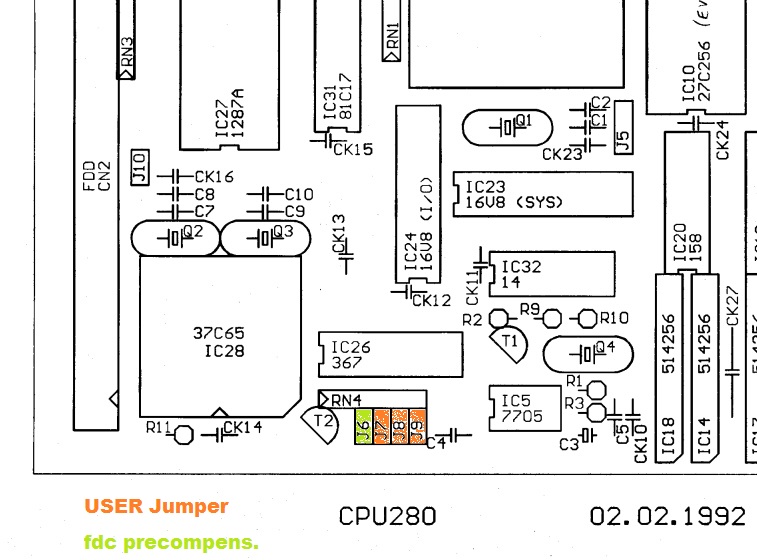
There really needs to be a "failsafe" jumper to force the firmware back to defaults and allow graceful recovery from such mistakes. Fritz mentioned something about "User jumper", but I am not sure what that refers to. I tried shorting the first jumper at the bottom edge of the board but that didn't accomplish anything.
What I have writen : Otherwise in loader.280 there is the check if user jumper UJ1 is set or if the checksum changed and then -> call setup.
From the loader.280
; Pruefen, ob waehrend RAM-Test eine Taste betaetigt wurde.    ## Test if during RAM-Check a key is pressed
; Bei DEL (oder geaenderter Checksum): Setup-Menu aufrufen.    ## if DEL or changed checksum call setup-menue

iopage	boardp
	in	a,(gpi)		; User-Jumper lesen  # read user jumper
	bit	b$uj1,a
	#################
        jp	z,boots1	; UJ1 gesteckt: ins Setup gehen (Defaults!)  ## if user jumper 1 is set goto setup
        ################
	ld	hl,(ChkSum)
	in	a,(CheckLo)
	cp	l		; Low-Bytes vergleichen  #compare low-bytes
	jp	nz,BootS	; verschieden: Setup!    #different -> setup
	in	a,(CheckHi)
	cp	h		; High-Bytes vergleichen #compare high-bytes
	jp	nz,BootS	; verschieden: Setup!    #different -> setup
	inchar			; inzwischen Taste betaetigt?   # was a normal key pressed ?
	jr	c,Boot		; nein: normal booten           # no: normal boot
	cp	DEL
	jr	nz,Boot		; nur bei DEL : Setup-Menu (sonst normal)  # only if DEL is pressed -> setup menue
Jumper:
J7 to J9 are user setable jumpers read by gpi
J10 internal reset of RTC (use only when power off)
From the manual:
J6-J9 Header 2x4, FDC-Precomp and User-Jumpers
----
so Jumper 7,8,9, are User-Jumpers and J7 must be the first user-jumper.
and if J7 is set the system should restore the default setup and boot to the configure menu. You must after that replace the J7
The time we got the Reh280 we had contact to each other and little problems were solved by phone calls or visits. The manual doesn't include every little information we had worked out and even it maybe that I'm wrong as I have no REH280 available to test.
-
 Attachment: hc_2199.jpg
(Size: 115.84KB, Downloaded 1082 times)
/*-----
fritz
-----*/
[Updated on: Wed, 05 July 2017 10:29] Report message to a moderator |
|
|
|
| Re: Interested in a Z280 SBC [message #3166 is a reply to message #3163] |
Wed, 05 July 2017 11:28 |
|
lowen
Messages: 226
Registered: August 2016
Location: Western NC USA
|
Senior Member |
|
|
fritzeflink wrote on Wed, 05 July 2017 13:00snhirsch_gmail.com wrote on Tue, 04 July 2017
There really needs to be a "failsafe" jumper to force the firmware back to defaults...
What I have writen : Otherwise in loader.280 there is the check if user jumper UJ1 is set or if the checksum changed and then -> call setup...
Useful information; thanks Fritz! It looks like J7 is connected to data bus bit 0, and the file 'cpu280.mac' defines b$uj1 as being bit 0, so it does indeed look like the code will do this with J7 closed at boot.
EDIT: Just got an email from PCBcart that the IDE boards have been delayed a few days; they are slated to ship July 8 at this point.
--
Bughlt: Sckmud
Shut her down Scotty, she's sucking mud again!
[Updated on: Wed, 05 July 2017 11:37] Report message to a moderator |
|
|
|
| Re: Interested in a Z280 SBC [message #3167 is a reply to message #3166] |
Wed, 05 July 2017 12:06 |
|
fritzeflink
Messages: 80
Registered: January 2017
Location: germany
|
Member |
|
|
From: Historie translated with google as I'm in a hurry
Was: searching for Jumper 7 to initialize setup
History file for the bootloader to the CPU280
------------------------------------------
(First release V1.0 on 17.11.90)
V1.01 from 16.12.90:
- Change: between OUT / JP now IN or 4xNOP instead of NOP due
Latest Errata Sheet.
- Change: Status detection 'Startup' via J7 instead of RTC reset.
- Change: save new checksum after exiting the setup.
- [Change: Default diskette format 'Reh 3.5 "HD' (1760k),
Buffer increases up to 512 directory entries, 880 blocks.
- Change: DMA in single byte mode instead of burst mode.
V1.02 of 19.01.91:
- Expansion: The loader also now supports the new track translation
As well as the explicit header numbers from the parameter block.
- Extension: The RAM disks are not generally deleted, but rather
The possibly already existing label is examined. If the label is intact
Nothing is deleted, with up to 5 faulty bytes is asked whether
And only 5 errors are mercilessly cleansed.
- Extension: The data required for the system start will be for the most part
Has already been created in the loader and sent in a global parameter block to the
BOOT routine of the BIOS.
- Change: In addition to J7, also for RTC reset 'Startup'.
- Change: Date of RAM disk DirLabels generally version date loader.
14.06.92 (still V1.02): added english messages (conditional assembly).
V1.02a of 27 June 1994:
- Changed Initialization of MDrive Directory to 32k (1024 Entries).
V1.13 of 15 February 1995:
- Completely rearranged loader structure to make use of the modular
Device driver sources of the CP / M-3 system BIOS. Most of the BIOS
Modules are now used within the loader, too. The version number of
The loader is the same as the system release
With the matching BIOS modules.
- Added support for booting the system file CPM3.SYS from every
Existent drive, including all pseudo-disks. Expanded setup to
Allow for appropriate selection of the boot drive.
- During boot, the RAM disks are now initialized with 1024 directory
Entries each.
- In the setup menu, the I / O device names are now listed to make
Selectioniting. However, it has been noted that the CPM3.SYS file
To be loaded might contain other definitions! The device names and
Their numbering is done from the LOADER portion within the EPROM only.
V1.13 of 14 March 1995:
- Fixed a bug in the auto-configuration code for MDrive directory size.
(The bug only with more than 1 MB of RAM.
Added:
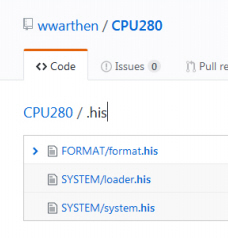
The .his-files are even at https://github.com/wwarthen/CPU280/ but I had to remember. Add: V1.01 and 1.02 are in german language only
-
Attachment: hc_483.jpg
(Size: 30.75KB, Downloaded 1057 times)
/*-----
fritz
-----*/
[Updated on: Wed, 05 July 2017 17:57] Report message to a moderator |
|
|
|
| Re: Interested in a Z280 SBC [message #3168 is a reply to message #3160] |
Wed, 05 July 2017 12:19 |
sarah
Messages: 15
Registered: October 2015
|
Junior Member |
|
|
lowen wrote on Wed, 05 July 2017 07:31Sorry for the delay in replying; I had a wisdom tooth extracted Friday, so I took it easy over the long weekend.....
Ow. Sorry to hear that. I've been to the dentist six or seven times this year, so I definitely sympathize. :-(
lowen wroteFirst, great that it is together and a portion of the board is working fine (otherwise you wouldn't get any text at all). Thanks for the good writeup on your experiences with the serial ports; no, they aren't 9-pin AT standard (they are actually designed to line up with a 25-pin connector's first 10 pins according to the docs). I need to write that up better and put it on the wiki, along with a wiring diagram.....
Oh, is that what the docs were getting at? I found the wording about the 25 pin connectors a little perplexing.
lowen wroteCurrent draw is good, and yes the third LED doesn't go out because the RAM test didn't pass.
The good news is that the Z280's bus is good, the system and I/O address decode is good, the lower 16 bits of the address is properly latched, the EPROMs are good, the DS12887A is good, the clocking is good, and you have good UART and LT1134 RS-232-TTL shifters.
Now, the areas that could be bad:
1.) The RAM itself. I'll be glad to swap you four more chips. This is the easiest thing to troubleshoot and is the most likely culprit.
2.) IC21 (GAL16V8-RAM). I tested this chip prior to shipping, but it's always possible that it could have lost some of its programming.
3.) IC22 (GAL16V8-CAS4). I tested this chip prior to shipping as well. IC21 and IC22 together produce the majority of the DRAM control.
4.) IC30 and IC4. Together these chips provide the synchronous timing chain that drives the critical DRAM timing, with the base CAS pulse width being determined by R8 and C6.
5.) R8 and C6. Your scope's trace at 50ns/div makes the CAS pulse look a tad long, but it also looks pretty smeared; what bandwidth scope is that? CAS is supposed to be about 20ns.
6.) IC19 and/or IC20. The mux is the heart of any DRAM circuit.
The first step would be to swap RAM, and I'll be glad to send you four from my working CPU280 in exchange for those four.
I'll take you up on that RAM swap offer if necessary, but let me poke around a little bit first. I'm hoping it's going to turn out to be something relatively simple, like a bad joint/bad socket/etc.
The bandwidth on the scope is advertised as 100MHz, but I rarely use it for high speeds so I can't really say how good it is for high speed work. I can probably get a better image of that pulse with a little more attention to detail. Sadly I don't have a logic analyzer available at the moment. Hmm, come to think of it, my first try at capturing that pulse was much more square than the current image; but after going off to find the iPad to take a picture, and some more random poking around looking at other signals, by the time I was ready to take the picture and got back to the CAS pulse, that's what it looked like. More likely poor technique on my part than any sort of electrical issue.
How critical is the over/under on the width of that pulse? The data sheet for the RAM said that CAS needed to be something like 13ns-10,000ns... but I have no idea how the width of the CAS pulse will affect the rest of the circuit. I thought about trying to replace my 120pf C6 with 100pf, or maybe 82pf, just to see what might happen, but figured I should get some feedback and do some more careful checking before I start ripping apart the board...
I'll see if I can find the German version of the docs with the timing diagram. A copy on the wiki would also be nice at some point.
I'll fiddle with the board some more when I get a chance and let you know what I discover.
Thanks for the help!
Sarah
|
|
|
|
| Re: Interested in a Z280 SBC [message #3169 is a reply to message #3168] |
Wed, 05 July 2017 12:41 |
|
lowen
Messages: 226
Registered: August 2016
Location: Western NC USA
|
Senior Member |
|
|
I just uploaded the German version to the media section of the CPU280 page on the wiki here. Look on PDF page 22.
Let me know if you want to swap chips, and we'll get that going.
--
Bughlt: Sckmud
Shut her down Scotty, she's sucking mud again!
[Updated on: Wed, 05 July 2017 12:41] Report message to a moderator |
|
|
|
|
|
Current Time: Thu Apr 25 20:29:42 PDT 2024
Total time taken to generate the page: 0.01708 seconds
|
 RetroBrew Computers Forum
 Members
 Search
 Help
Help Login
Login Home
Home


")
