Table of Contents
ECB-4PIO
The ECB-4PIO is a digital input and output interface board. It's a 100x160mm Eurocard Kontron compatible board designed to work with the Z80 SBC V2 processor board.
Features
- Kontron compatible Eurocard interface.
- Up to four digital input/output connectors compatible with the jk82-PIO-WRAP board by Janich & Klass.
- Two eight bit ports per connector with strobe and ready signals.
- Z80 interrupt mode 2 compatible.
Pictures
Revision 3 board:
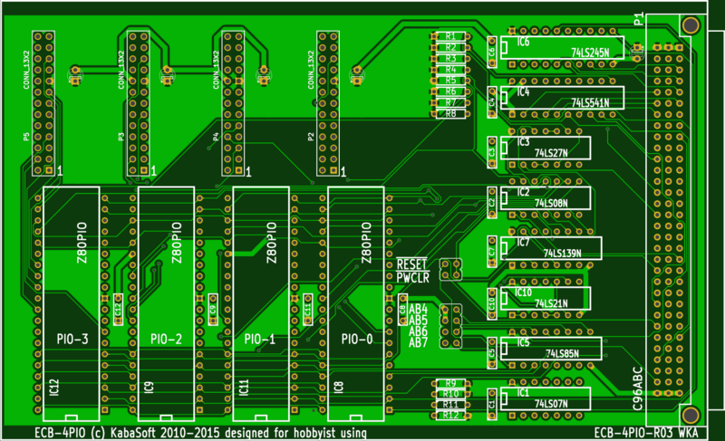
Revision 3 board (port 90h Kontron reset):

Acknowledgements
The ECB-4PIO was developed by Wolfgange Kabatzke based on a similar design by Janich & Klass.
General characteristics
- The ECB-4PIO board supports up to four Z80A-PIO's
- Power consumption is typically 400mA at 4MHz at 5V.
- ECB-4PIO is full IM2-interruptible. The bus control logic allows RETI-detection for the internal PIO. IEI and IEO are wired to look ahead. Even with a partial assembly the IEI/IEO Daisy Chain is fully preserved.
Z80 PIO Operating modes
- Mode 0: Output Mode
- Mode 1: Input Mode
- Mode 2: Bidirectional Mode
- Mode 3: Bit Control Mode
Hardware Documentation
Schematics
Board Layout
PCB Gerber files
:boards:ecb:4pio:ecb-4pio-r03-gerber.zip
Pin assignment of parallel ports
This pinout is compatible to jk82-PIO-WRAP by Janich & Klass.
Each PIO has a 26-pin connector associated with the following pin assignments:

Jumper Assignment S1 & S2
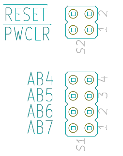
The board occupies 16 I/O addresses. Jumper S1 defines the start address. Jumpers for A4 to A7 of S1 define the upper 4 bits of the start address. Refer to the address guidelines to identify available address for your system.
A4 7-8 POSN 4
A5 5-6 POSN 3
A6 3-4 POSN 2
A7 1-2 POSN 1
The default settings for the ECB-4PIO is a base address of 0x20h:
A4 7-8 ON
A5 5-6 OFF
A6 3-4 ON
A7 1-2 ON
For address setting is important to note that “ON” is a zero and “OFF” is a one (The switches are set to GND!).
Jumper S2 is the board reset select option. Jumper position 1 (1-2) to set legacy mode. Jumper position 2 (3-4) to select Kontron mode. All board in your system should be set to have matching settings. Check the SBC V2 Errata notes if you are intending to run on Kontron compatibility mode.
3-4 set to /RESET (C31, N8VEM)
1-2 set to /PWRCLR (C26, Kontron compatibility)
Address settings of the I/O ports
Each Z80 PIO chip uses four addresses out of the sixteen I/O addresses decoded by the ECB-4PIO board. The upper 4 bits of the address are set by jumpers for A4 to A7 using S1. The mapping of the addresses to the PIO's is shown below, assuming a base address 0x20:
| A7 | A6 | A5 | A4 | A3 | A2 | A1 | A0 | ADDR | FUNCTION |
|---|---|---|---|---|---|---|---|---|---|
| X | X | X | X | 0 | 0 | 0 | 0 | 0x20 | PIO 0 DATA Channel A |
| X | X | X | X | 0 | 0 | 0 | 1 | 0x21 | PIO 0 DATA Channel B |
| X | X | X | X | 0 | 0 | 1 | 0 | 0x22 | PIO 0 CTRL Channel A |
| X | X | X | X | 0 | 0 | 1 | 1 | 0x23 | PIO 0 CTRL Channel B |
| X | X | X | X | 0 | 1 | 0 | 0 | 0x24 | PIO 1 DATA Channel A |
| X | X | X | X | 0 | 1 | 0 | 1 | 0x25 | PIO 1 DATA Channel B |
| X | X | X | X | 0 | 1 | 1 | 0 | 0x26 | PIO 1 CTRL Channel A |
| X | X | X | X | 0 | 1 | 1 | 1 | 0x27 | PIO 1 CTRL Channel B |
| X | X | X | X | 1 | 0 | 0 | 0 | 0x28 | PIO 2 DATA Channel A |
| X | X | X | X | 1 | 0 | 0 | 1 | 0x29 | PIO 2 DATA Channel B |
| X | X | X | X | 1 | 0 | 1 | 0 | 0x2A | PIO 2 CTRL Channel A |
| X | X | X | X | 1 | 0 | 1 | 1 | 0x2B | PIO 2 CTRL Channel B |
| X | X | X | X | 1 | 1 | 0 | 0 | 0x2C | PIO 3 DATA Channel A |
| X | X | X | X | 1 | 1 | 0 | 1 | 0x2D | PIO 3 DATA Channel B |
| X | X | X | X | 1 | 1 | 1 | 0 | 0x2E | PIO 3 CTRL Channel A |
| X | X | X | X | 1 | 1 | 1 | 1 | 0x2F | PIO 3 CTRL Channel B |
Attention! The assignment of A0 and A1 changed to the following: A0 → B/~A, A1 → C/~D. This is conform to the ZILOG-datasheets and other applications all around the world. At the JP82-PIO WRAP this was changed.
BOM
IC1 74LS07
IC2 74LS08
IC3 74LS27
IC4 74LS541
IC5 74LS85
IC6 74LS245
IC7 74LS139
IC8-IC12 Z80A-PIO
R1-R12 4.7K Resistor
C1-C12 100nF Ceramic
C20-C24 100uF Electrolytic
S1 2×2 pin header
S2 2×4 pin header
P 1 VG-96 connector (a,b,c)
P 2-5 Header 4 x 26pin (2 x 13pin)
Socket: 3 x 14pin, 2 x 16pin, 2 x 20pin, 4 x 40pin.
IEI/IEO-Daisy-Chain
The four PIO are able to use vector interrupts and are prioritized in a daisy chain. The daisy chain is connected to a carry-look-ahead logic, so that the processing delay is in the range of 10 to 20ns.
BUS —> PIO 0 —> PIO 1 —→ PIO 2 —> PIO 3 —→ BUS
IEI IEO IEI IEO IEI IEO IEI IEO
Through pull-up resistors of the IEO PIO-0, PIO-1, PIO-2 and PIO-3 is a proper function of the daisy chain be guaranteed even if not all 4 PIO are fitted. PIO's must be fitted in order PIO-0 to PIO-1, -2, -3 in order to maintain the daisy chain.
BAI/BAO-Daisy-Chain
The Bus acknowledge Daisy-Chain BAI/BAO is hard wired on the ECB-4PIO since the board is only for the ECB bus (compatible to) KONTRON.
Software
The ECB-4PIO is not currently supported by ROMWBW or UNABIOS.
Test software is available here:
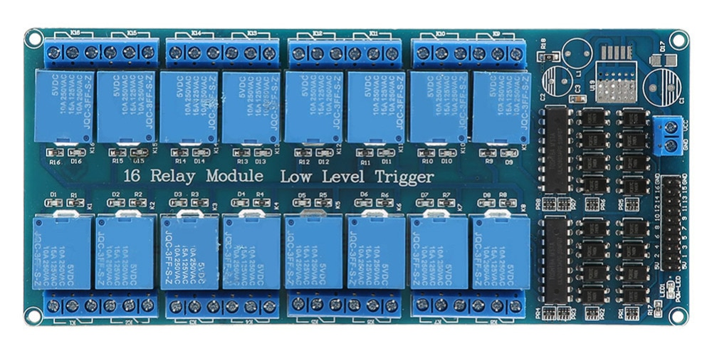
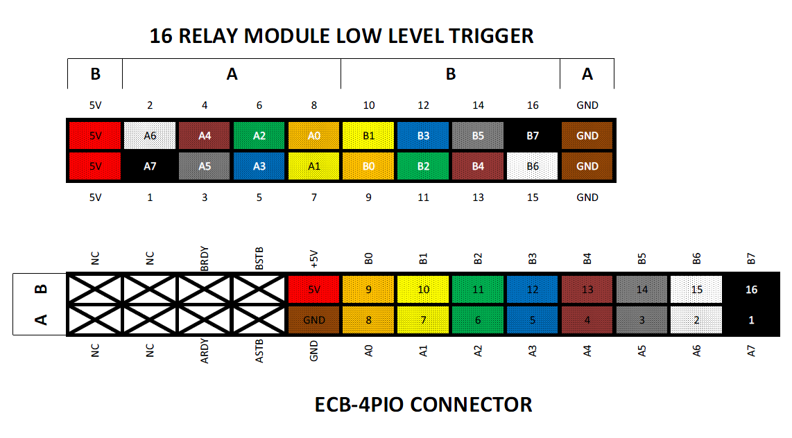
Applications
Example connection to a 16 bit relay board:
Resources
| Filename | Filesize | Last modified |
|---|---|---|
| 4piotst.zip | 4.6 KiB | 2018/09/09 00:38 |
| ecb-4pio-jumpers-1.png | 8.5 KiB | 2018/09/01 10:26 |
| ecb-4pio-pcb-r003.png | 277.2 KiB | 2018/09/02 01:20 |
| ecb-4pio-pinout.png | 16.4 KiB | 2018/09/01 10:26 |
| ecb-4pio-r03-gerber.zip | 84.9 KiB | 2015/11/01 23:23 |
| ecb-4pio-r03.jpg | 113.5 KiB | 2018/10/14 05:32 |
| ecb-4pio-relayboard.png | 703.5 KiB | 2019/04/08 06:49 |
| ecb-4pio-relayboardwiring.png | 130.8 KiB | 2019/04/08 06:49 |
| ecb-4pio_finished_and_complete_assembled.jpg | 660.6 KiB | 2015/11/01 04:07 |
| printing_ecb-4pio-r03-brd.pdf | 663.8 KiB | 2015/11/01 04:07 |
| printing_ecb-4pio-r03-sch.pdf | 197.3 KiB | 2015/11/01 04:07 |
| zilog_z80-pio_technical_manual.pdf | 25.8 MiB | 2018/09/09 00:37 |