Build procedure for Tiny68K Kit#2
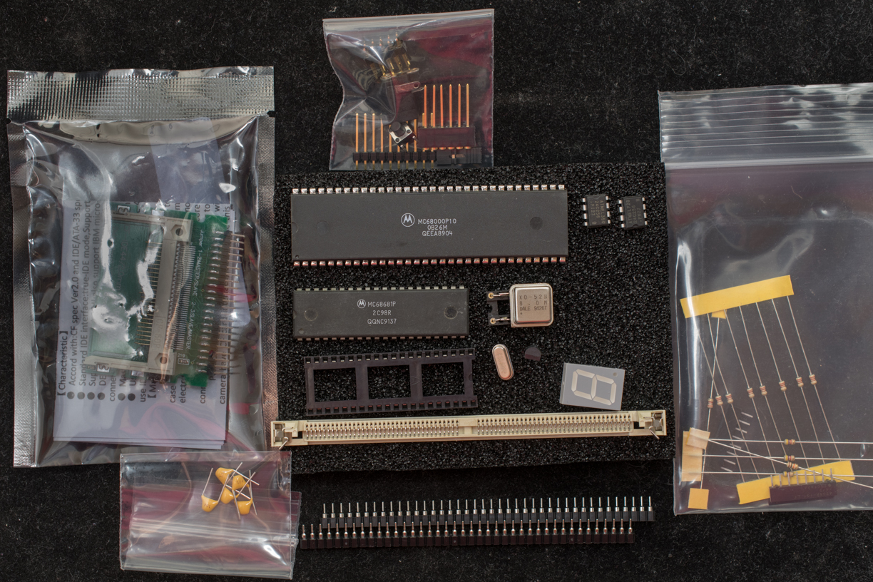
Kit #2 contains a partially assembled pc board where SMT resistors and capacitors are assembled and Altera EPM7128 is assembled and programmed. Included with Kit #2 are also bags of resistors, capacitors, hardware, and active components as shown in the photo below.
A high-resolution photo of the partial assembled board is below for reference
- Do not populate R11 and R15
- Install 5 bypass capacitors, C4-C8
- Install 3.6864MHz crystal, Y1
- The kit includes 2pcs 40-pin breakaway female socket strips. Break each 40-pin strip into a 32-pin strip and two 4-pin strips.
- Use four 4-pin strips as sockets for U5 and U7.
- Install a 4-pin socket for the 8MHz oscillator, U4
- Solder two terminals of T1 with a jumper wire. This is the write protect line for serial EEPROM, U5. Without the jumper U5 is writable.
- Install SIP 4.7K ohm resistor packs, R1 & R2. Observe the polarity of the resistor pack: pin 1 of the resistor pack is a square pad on the pc board that should match with pin 1 of the resistor pack (marked with a dot).
- Install the 7-segment LED display, D1. The decimal point is nearest to the pcb corner
- Install push button for reset, S1. The pc board footprint is slightly too wide, so the legs of the push button need to spread a tiny bit to accommodate the wide footprint.
- MCP130 voltage supervisor, U6. Line up the flat side of the package with the flat side of the silk screen.
- 2×5 header for Altera programming header, P2
- 2.5mm power jack, J1. The jack fits loosely on the pc board, so position the part in the desired orientation before soldering.
- (Optional step) Connect USB blaster to programming header, P2 (the stripe of programming ribbon line up with pin 2 of P2), apply 5V via the 2.5mm power jack (center is +5V, barrel is ground), verify the CPLD is programmed correctly.
- Install 2-terminal headers at T18/19, T20/21. This selects which serial EEPROM is the boot flash.
- Install two 32-pin socket strips as socket for 68000, U1.
- Install 40-pin socket for 68681, U3.
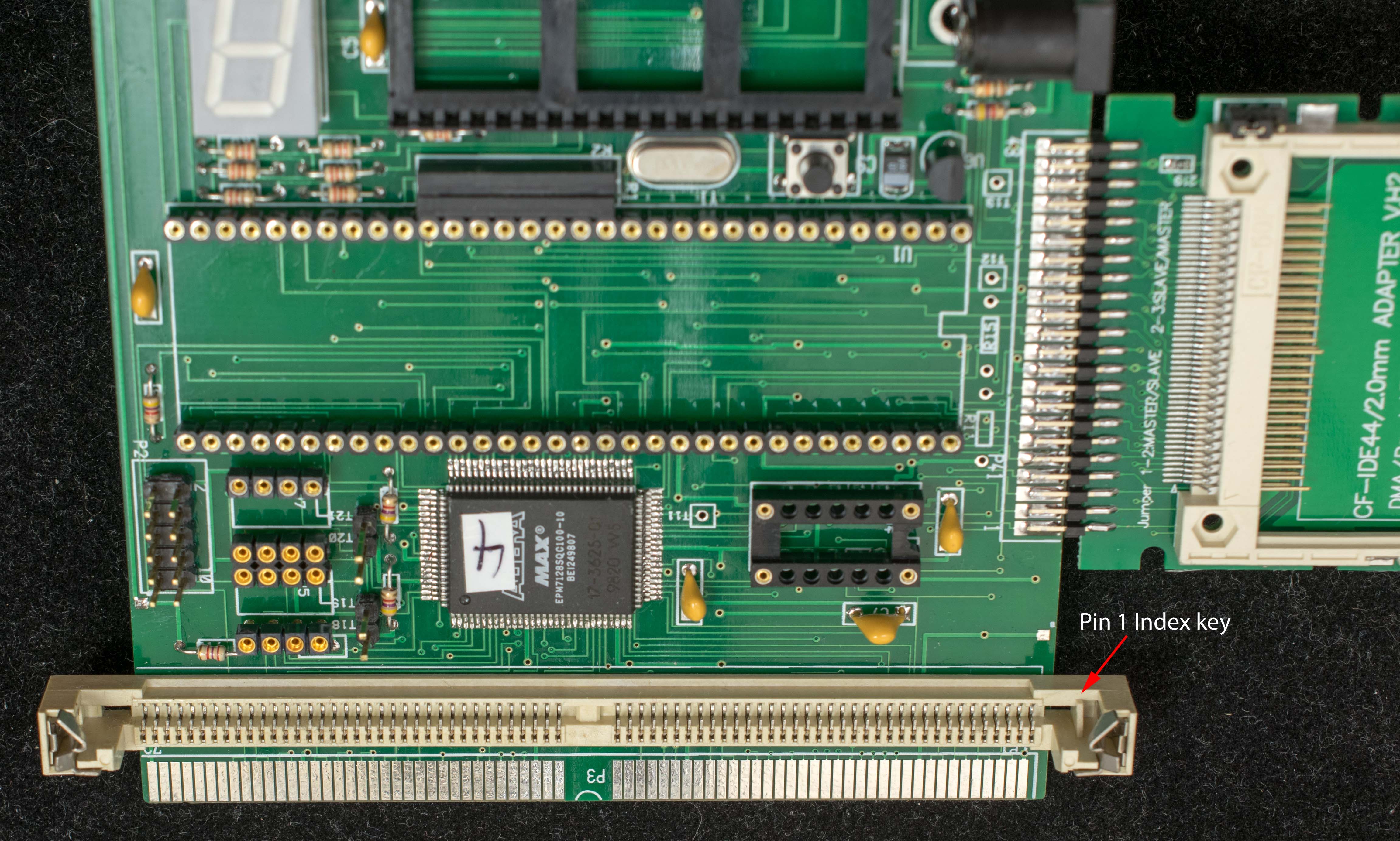
- Install SIMM72 socket, P1. Observe the polarity of the SIMM socket: The pin 1 index key of the socket must line up with pin 1 of silkscreen. Refer to the photo below for index key of the socket.
- 6-pin header for the console serial port. Two type of headers are included in the kit. One is 6-pin male-to-male wire-wrap strip, the other is 6-pin male-to-female wire-wrap strip. Select the header best fit your setup.
- Install a 24C256 in U5 and install a shorting block between T18/19. This is the default boot flash. The second boot flash in U7 is optional.
- Install 44-pin IDE-CF module, keep the module at the same level (another word, in the same plane) as the board before soldering. The assembly of Tiny68K is completed!
completed Tiny68K board with empty sockets
Photo shows the proper orientation of the SIMM socket
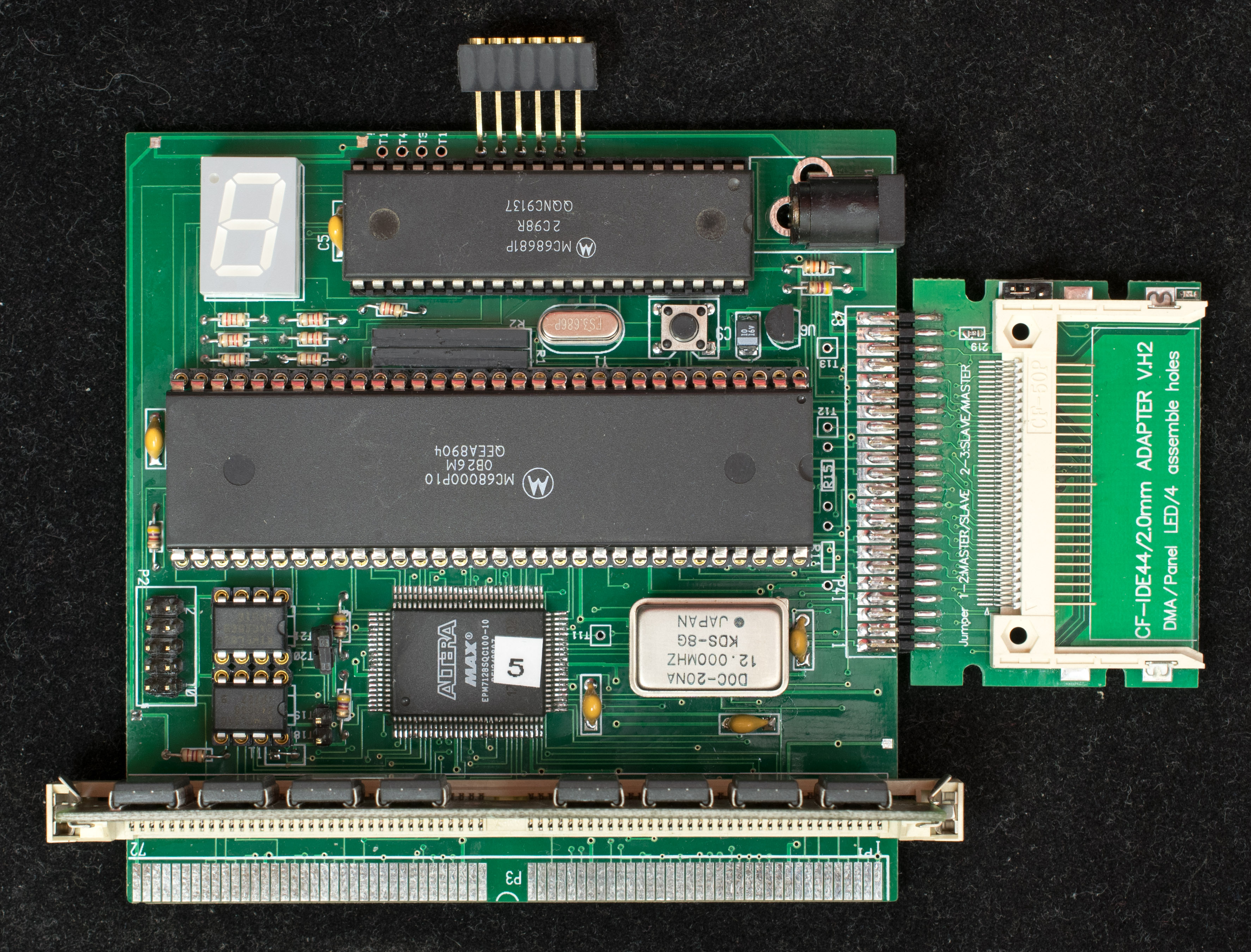
Completed board with components, component side
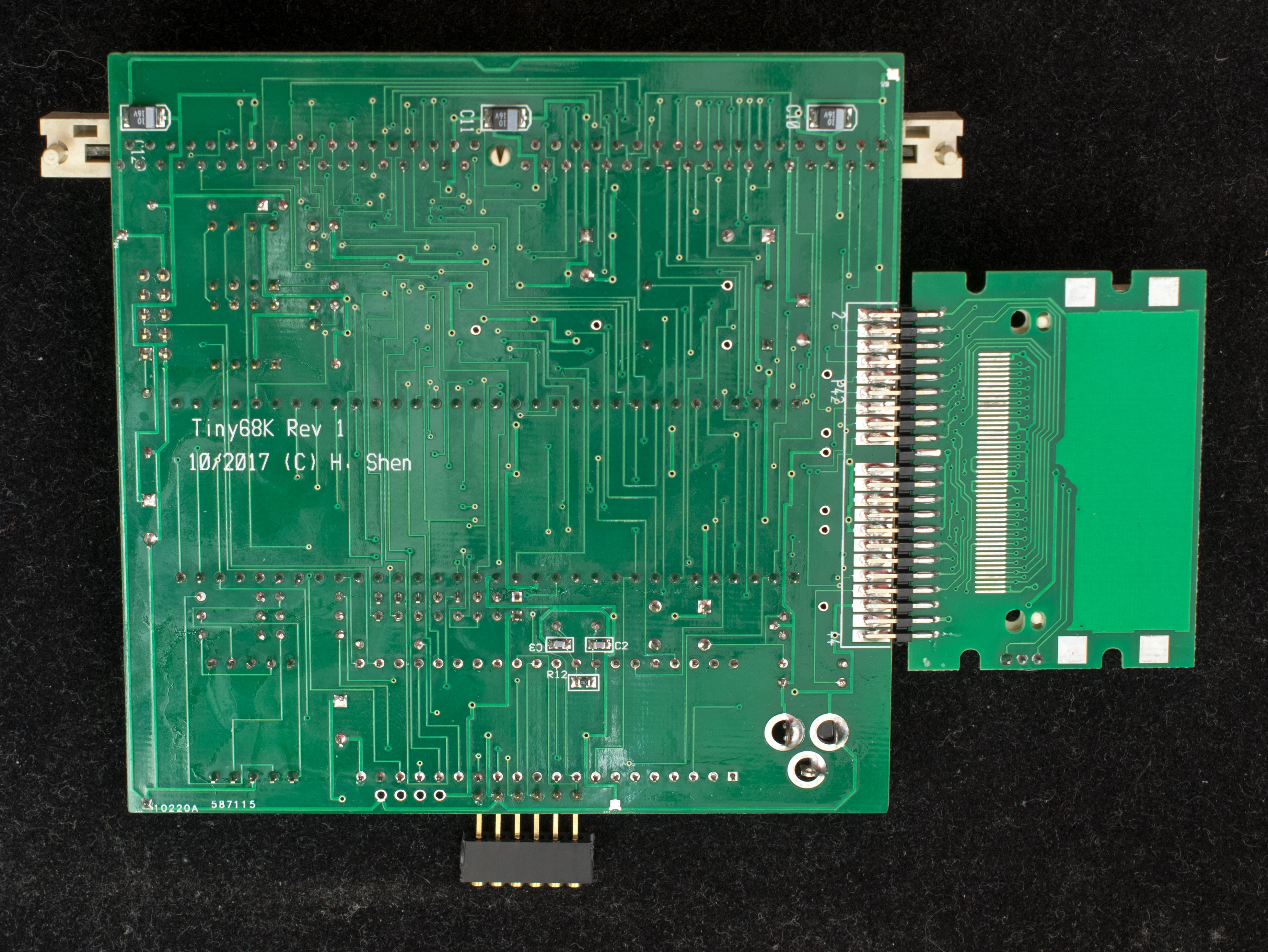
Completed board with components, solder side


